![]()
Owner: Tom Bauer (410) 549-6649 mailto:waterloospecialties@gmail.com
STEERING UPGRADES: POWER STEERING CONVERSION FOR M35-SERIES TRUCKS
Thank you for purchasing our Power Steering Conversion kit.
This kit uses a Saginaw Model 710 steering box.
This kit is made with all new parts and is supplied with a rebuilt box.
This power steering conversion is of very high quality but if you drive your truck on a public road or highway with this steering conversion installed, you do so at your own risk. While we have successfully used this kit on 3 of our trucks for more than 15 years with no issues, there are factors beyond our control when you install this kit, so please understand that Waterloo Specialties assumes neither risk nor liability once your purchased steering kit is shipped to you.
Please read these instructions before you begin, it will give you a better understanding of the installation process.
Price includes unlimited technical support. If you can remove the radiator or fender and drill holes in the frame, you can install this kit.
Tools you will need:
1/4” drill bit
1/2” drill bit
5/8” drill bit
1 1/2” metal hole saw
3/4” metal hole saw
wrenches and sockets 7/16, 1/2, 9/16, 5/8, 11/16, 3/4, 15/16 etc.
torque wrench good to 200 ft lb
|
POWER STEERING CONVERSION KIT: INSTALLATION INSTRUCTIONS |
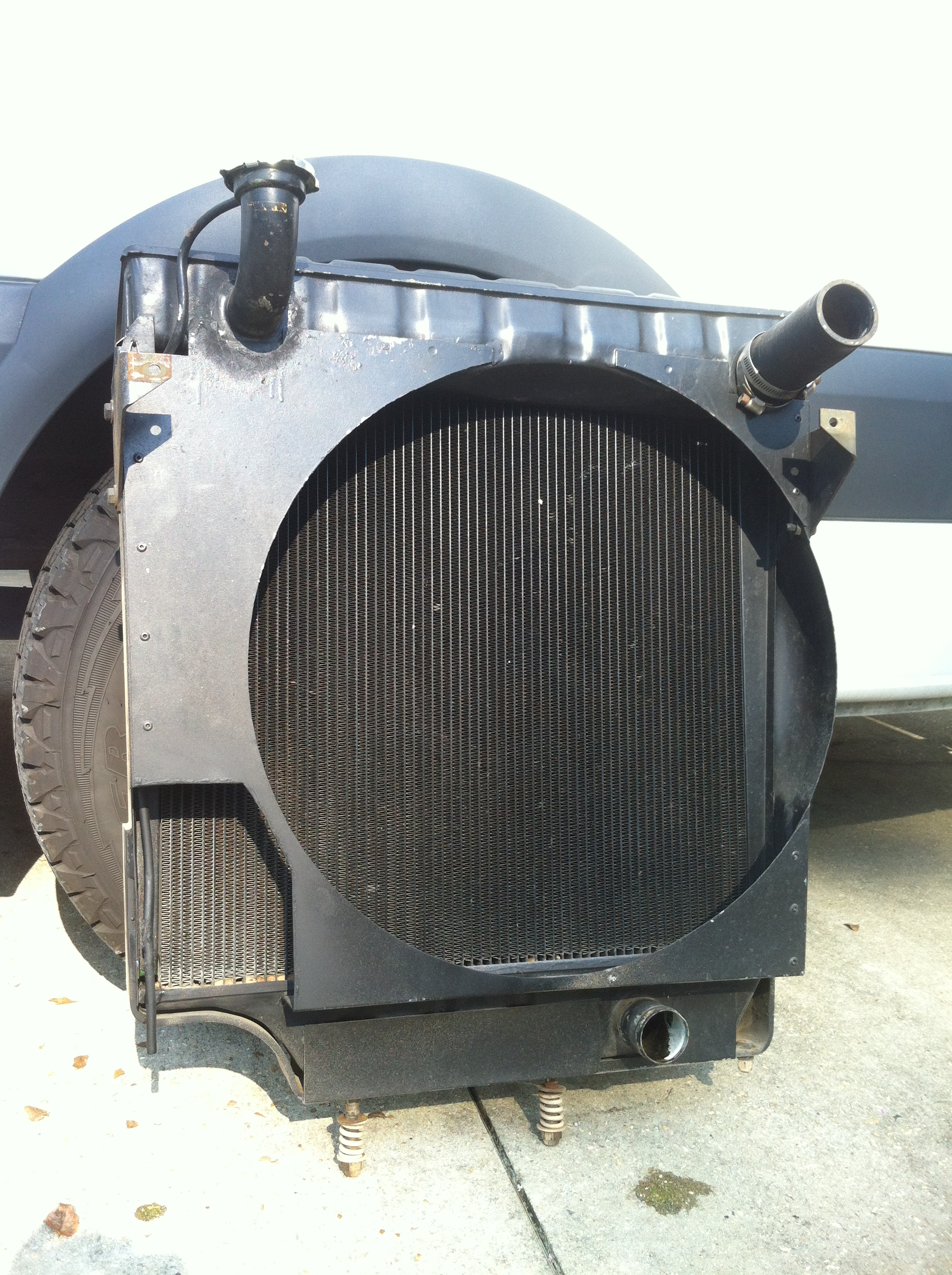
FIG 2
- Remove left front fender. By doing this you avoid removing the radiator. The only down side to this is the 3 bolts that hold the fender to the cab may be rusty but this is by far the best choice. Trim the fan shroud now FIG 2, pattern included. Radiator shown removed for clarity.
- Remove the left front wheel/tire, old drag link, and old Pittman arm. After removing the old drag link, it is very important you re-torque the 4 nuts holding the steering arm to the knuckle. Torque is 130 – 140 ft lb.
- Remove the steering wheel next, while the column and box are still in place.
- Remove the old manual steering box. There are a few tricks to doing this.You can take the cover off the box while it is in the truck, and then pull out the Pittman arm shaft, making more room to get to get the box housing and column out. Tip: Back out the cover bolts as far as room will allow and then cut off the bolt between the cover and box so you can more easily get the cover off.
- With the old steering box out of the truck, remove the cover on front of timing case of engine. Clean the old gasket off and install the pump with supplied gasket and some good gasket sealer. Do not use any of the silicone gasket makers, something like Permatex 3H is recommended.
- The new steering box mounts on the outside of the frame with the mounting bracket on top of the frame and the large reinforcement inside the frame rail. The next steps shows you how to mount the bracket and reinforcement.
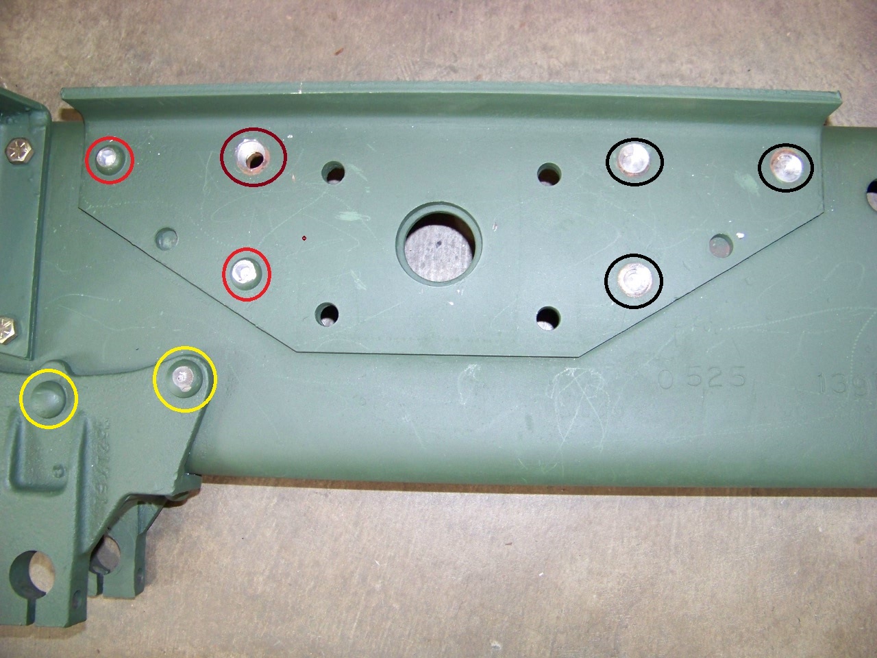
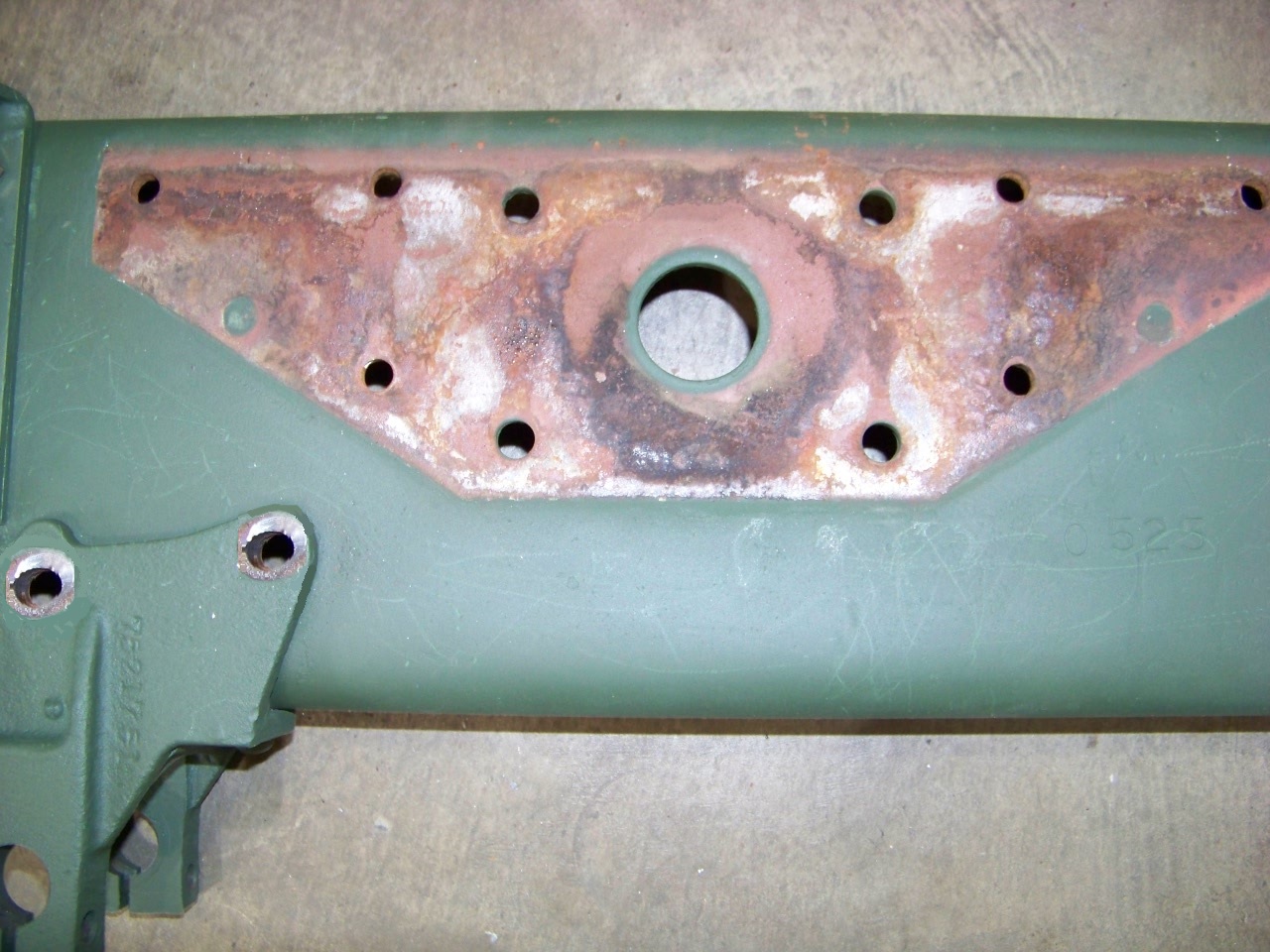
FIG 3 |
FIG 4 |
- Remove any bolts, rivets, etc., that may be in the way of the frame reinforcement; this includes the plate on the outside of the frame that was for the old steering box.
TIP: Shown in FIG 3, grind a flat area on the head of all the rivets , as shown in yellow circle, then center punch the rivet right in the center and drill a 5/16” hole,as shown in red circle, but not all the way through: drill only to the far side of the frame, this will be about 3/4 inch. Do this for all 8 rivits. Then with a 5/8" drill, drill off the head of all the rivets, as shown in black circle . With a 1/4” punch, drive the rest of the rivet out, as shown in brown circle . Do this for all 8 rivets and remove the plate. The rivits are put in red hot and when they are rivited it makes them very tight in the frame. Drilling a hole in them releases the pressure and they will punch out easily. Frame will look like FIG 4. Remove the bracket for the grill brace from the top of the frame.
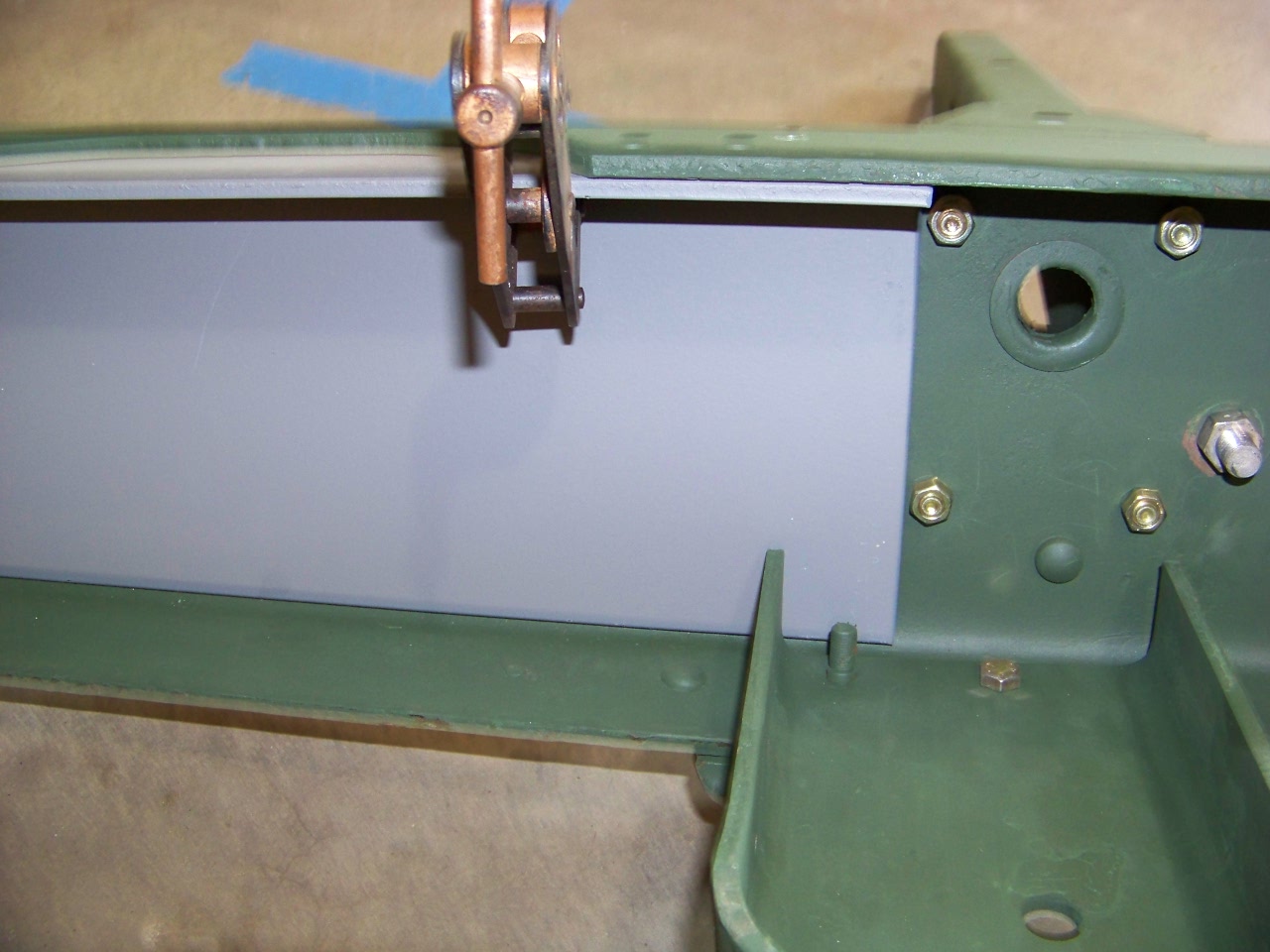
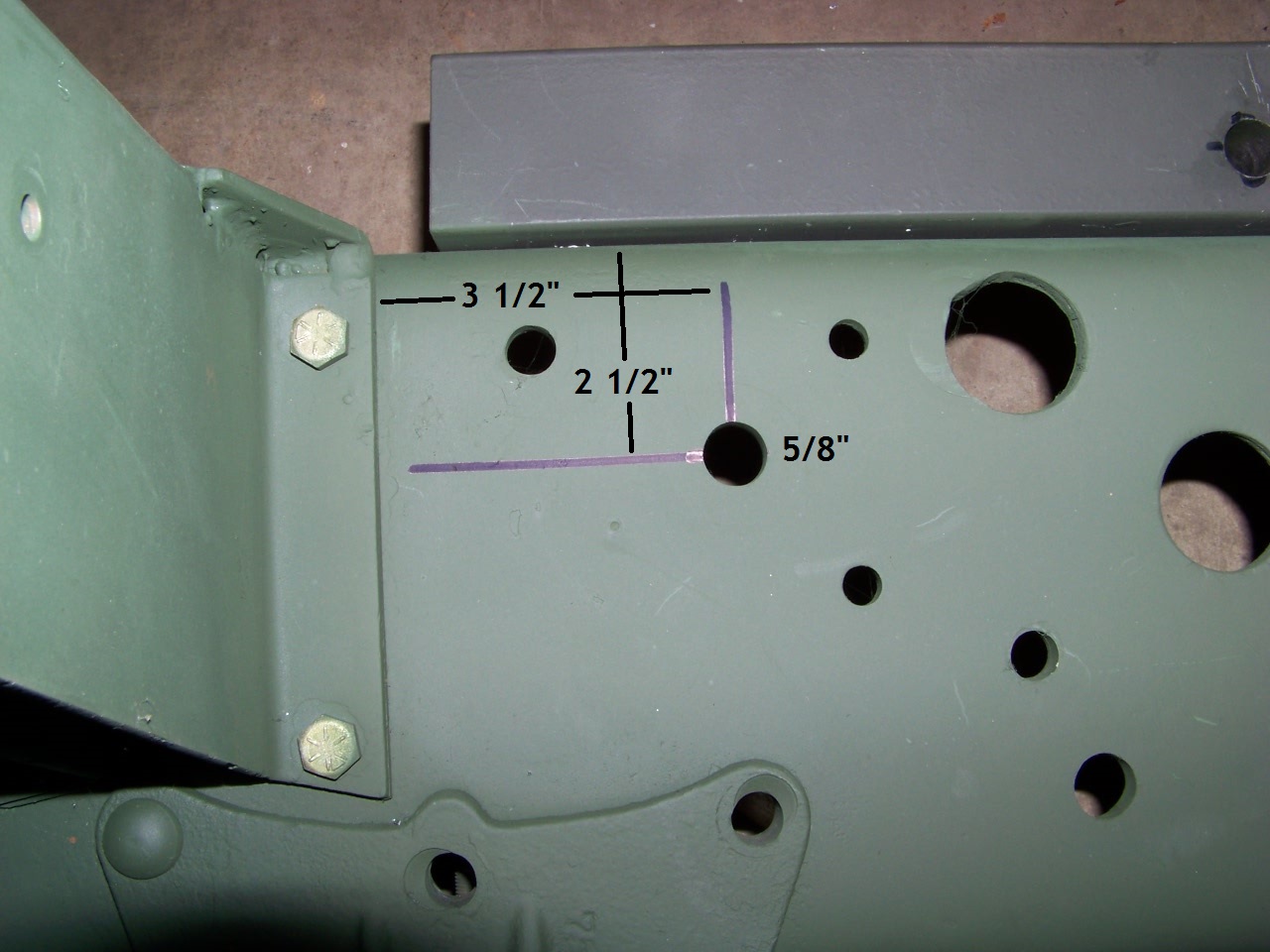
FIG 5 |
FIG 6 |
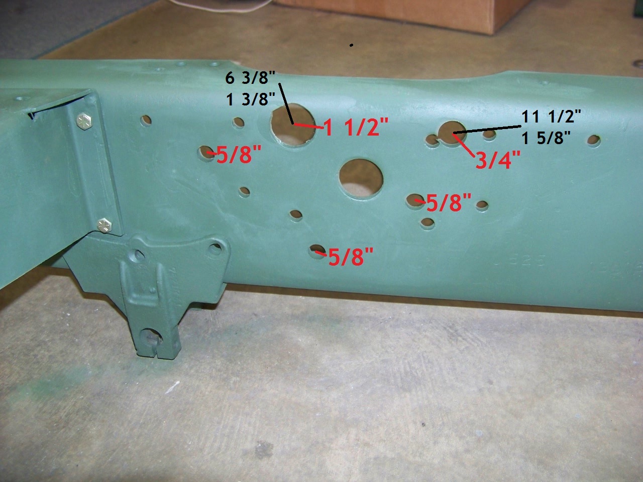
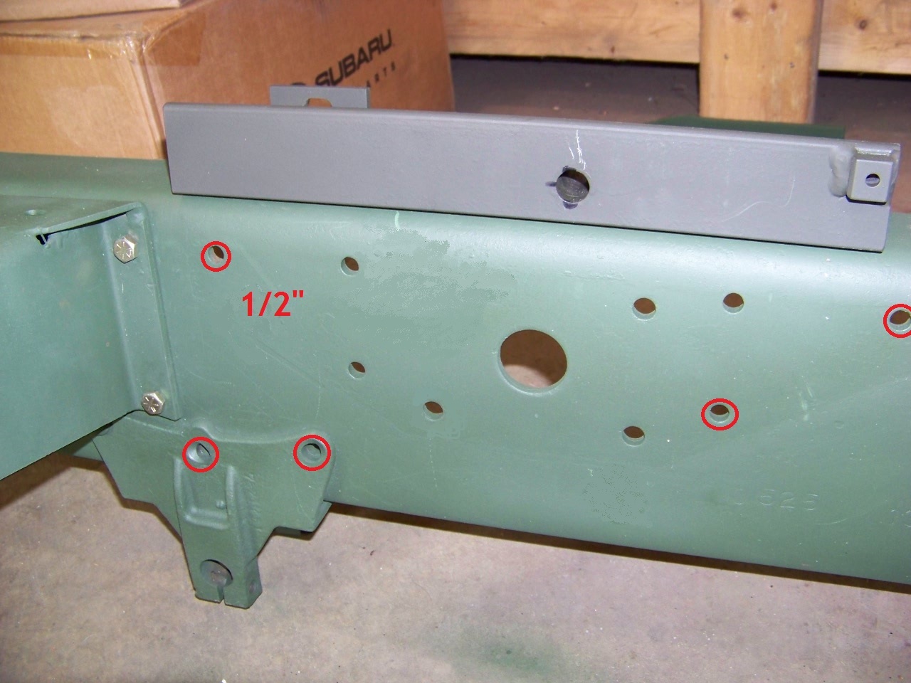
FIG 7 |
FIG 8 |
- Place the large reinforcement inside the frame, with the front edge just behind the bolts or rivits that hold the fender support FIG 5. Be sure there is nothing between it and the frame, then clamp the inner plate tightly in place up against the top of the frame and also against the inside of the frame before drilling. You can mark these 5 holes shown in red FIG 8 and then drill them in a drill press, or drill them in place. Drill them to 3/8" first and then enlarge these 5 holes to 1/2”. This will help them to be centered on each other. Remove all burrs and bolt the plate in place with the 5 bolts provided, (bag #1) the front upper bolt must be placed with the head of the bolt inside the frame or it will interfere with the front bolt for the top bracket. These five 1/2” bolts go in the locations shown in red FIG 8.
- Locate the front 5/8" hole shown in FIG 6 along with the 2 locations shown in FIG 7. Drill these 3 holes with a 1/4" drill for a starter hole. Then drill the front hole to 1/2" and finally 5/8". Use the 1 1/2" and 3/4" hole saw to make the other 2 holes in FIG 7. This is with the inner plate bolted in place. The 1 1/2" hole is 6 3/8" back from rear of fender support and 1 3/8" down from top of frame. The 3/4" hole is 11 1/2" back and 1 5/8" down.
- Place the top mounting bracket on top of frame, the front end should be very close to 1/2” back from the rear edge of the fender support bracket FIG 6. Place the steering box spacer on with the long 5/8 bolt in the bracket and one of the short bolts in the front hole you just drilled. Be sure it is orinated as in FIG 15. Clamp it there tightly and drill the 1/4 pilot holes through frame from top, then enlarge to 1/2" and install 2 bolts, bag #2.
- Now with the box spacer in place you can use a 5/8 drill in the 2 remaining holes to mark the location with the tip of the drill. Remove spacer and drill those 2 holes to 5/8, best done with 1/4" drill, then 1/2", then 5/8". You should now have a frame looking like FIG 10.
![]()
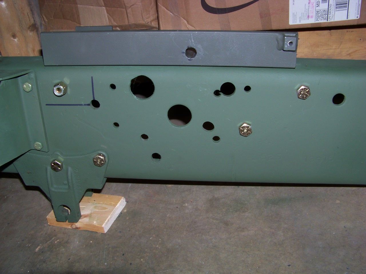
FIG 9 |
FIG 10 |
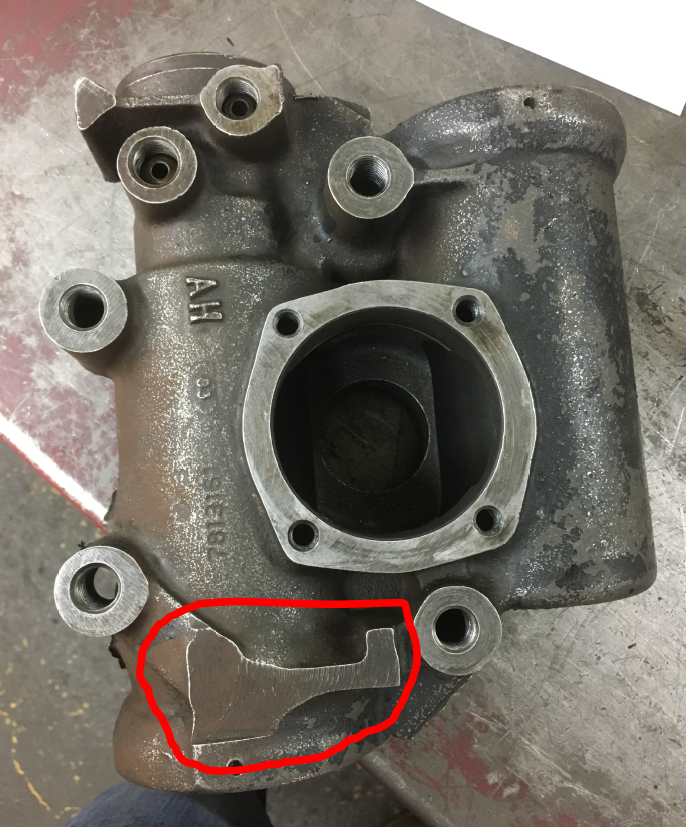
-Now you are almost ready to mount the box. A small change must be made to the box, remove the block shown in FIG 9. It can be done now or later but the pittman arm needs to clear this spot and it won't until this boss is removed.
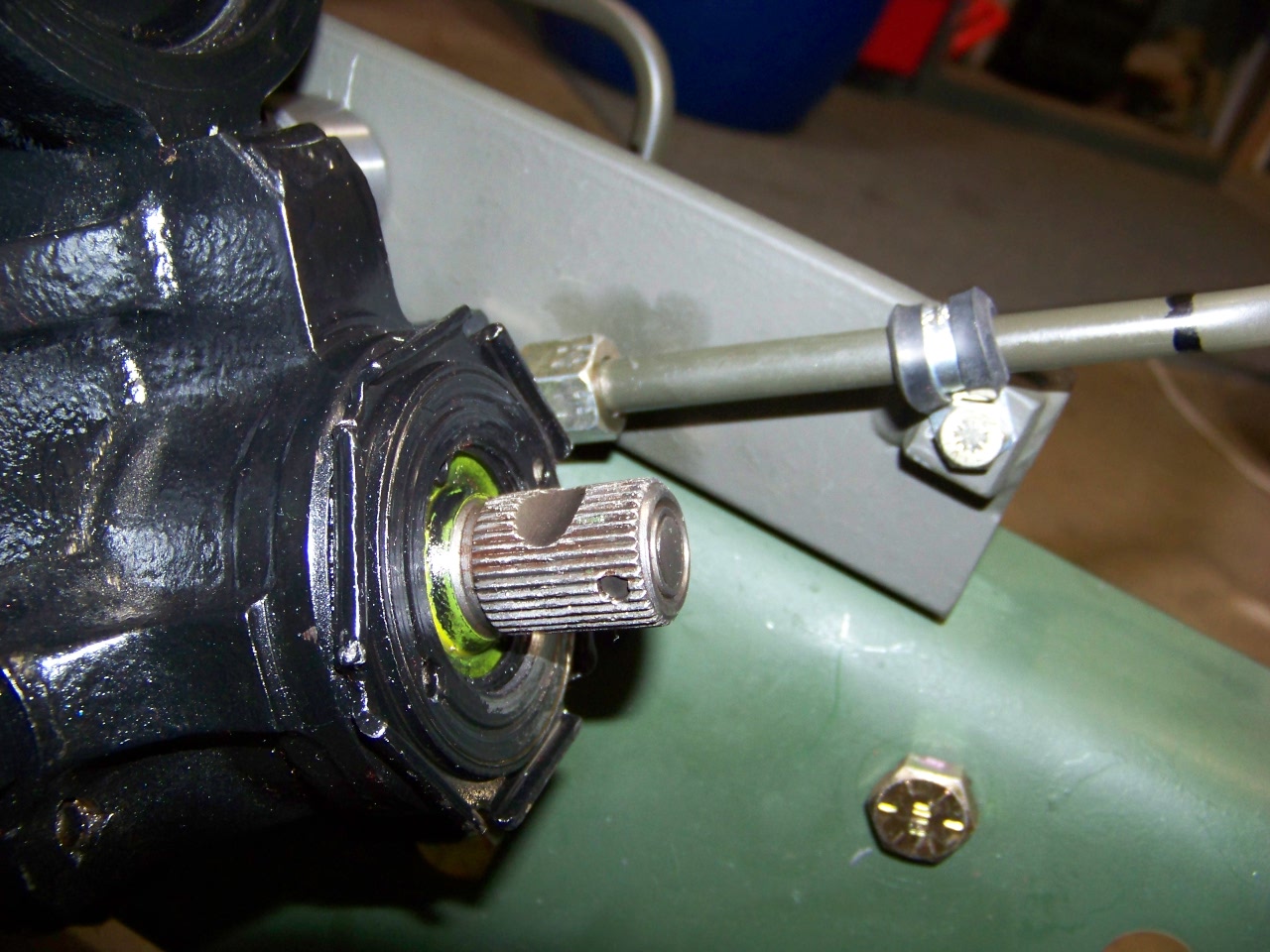
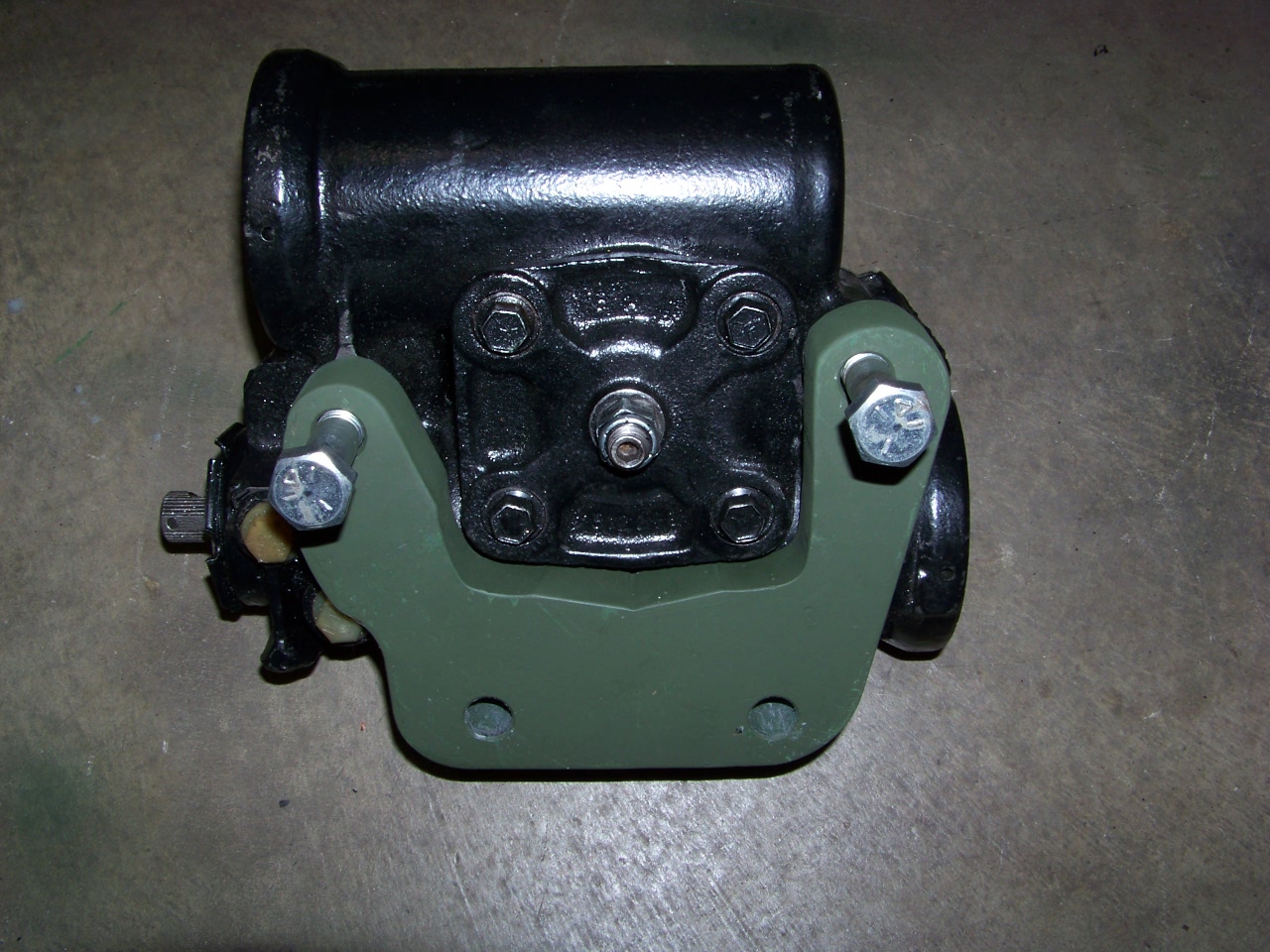
FIG 11 |
FIG
12 |
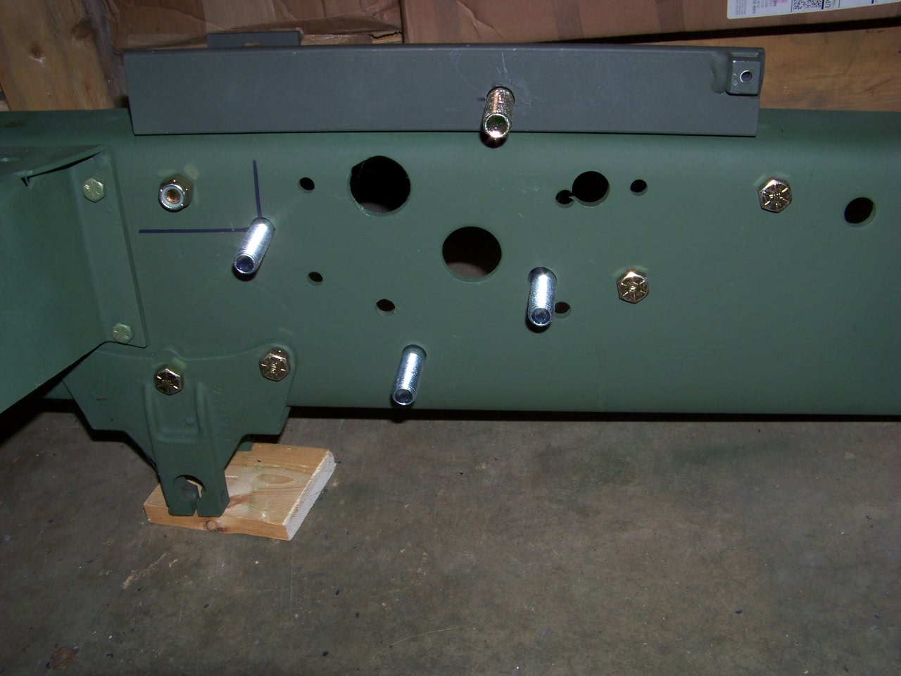
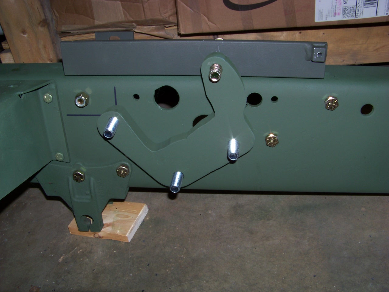
FIG 13 |
FIG 14 |
Casting may need to be ground down.
- Try the spacer on the steering box with all 4 bolts just to make sure it fits flush with all 4 bolt pads. FIG 12.
- Now put the 4 bolts in from the rear and the spacer on the bolts FIG 13 and FIG 14.
- First install the banjo fitting with the line on it (used to hold it from turning). Tighten the fitting with the line pointing parallel to the input shaft FIG 11, FIG 15, FIG 16. Use care tightening the banjo fitting, don't over tighten it.
- Now you are ready to mount the box and torque the 4 bolts to 188 ft lbs.
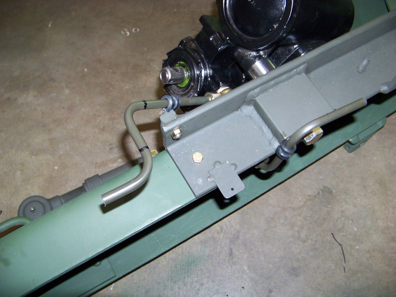
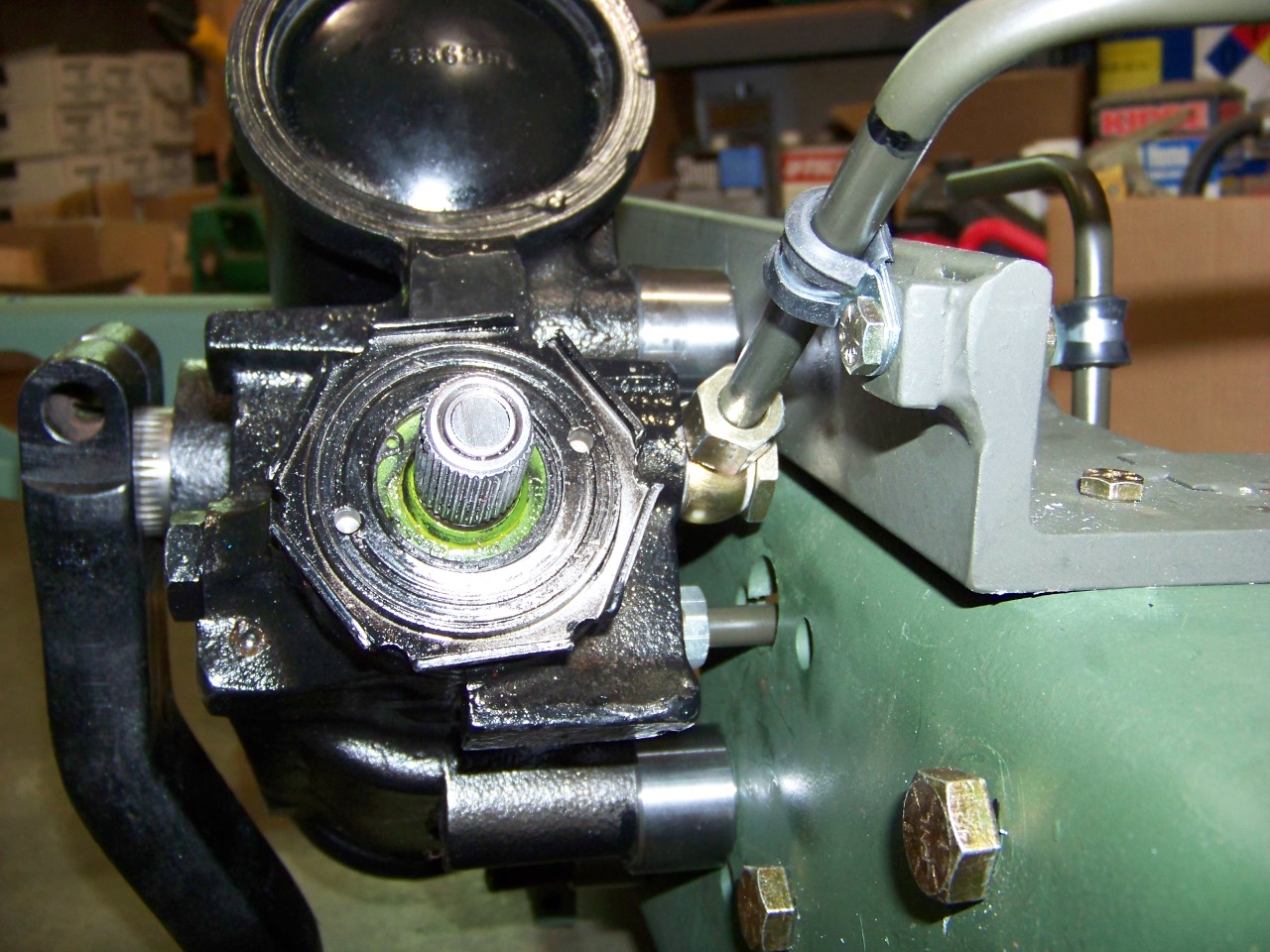
FIG 15 |
FIG
16 |
- Position the lines and secure
lines with clamps FIG 15 and FIG 16.
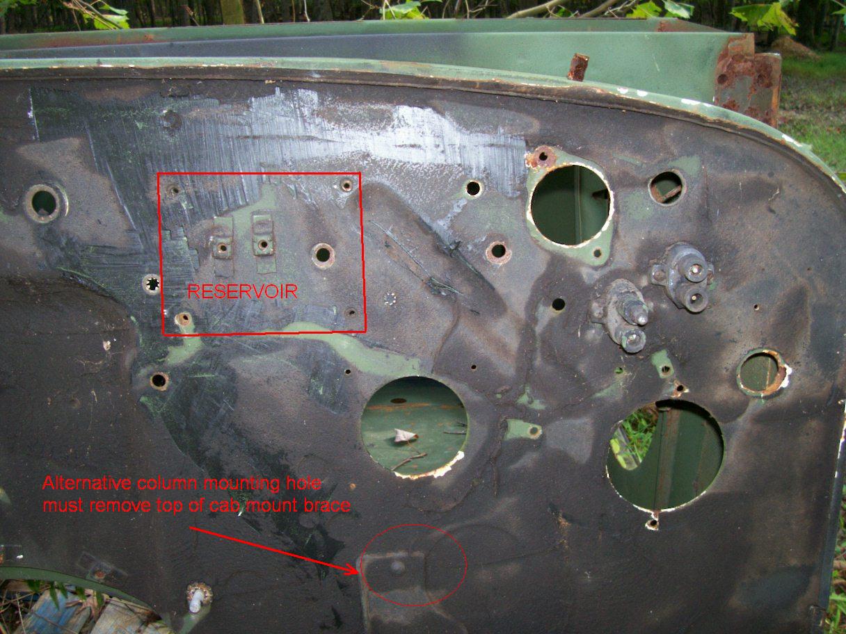
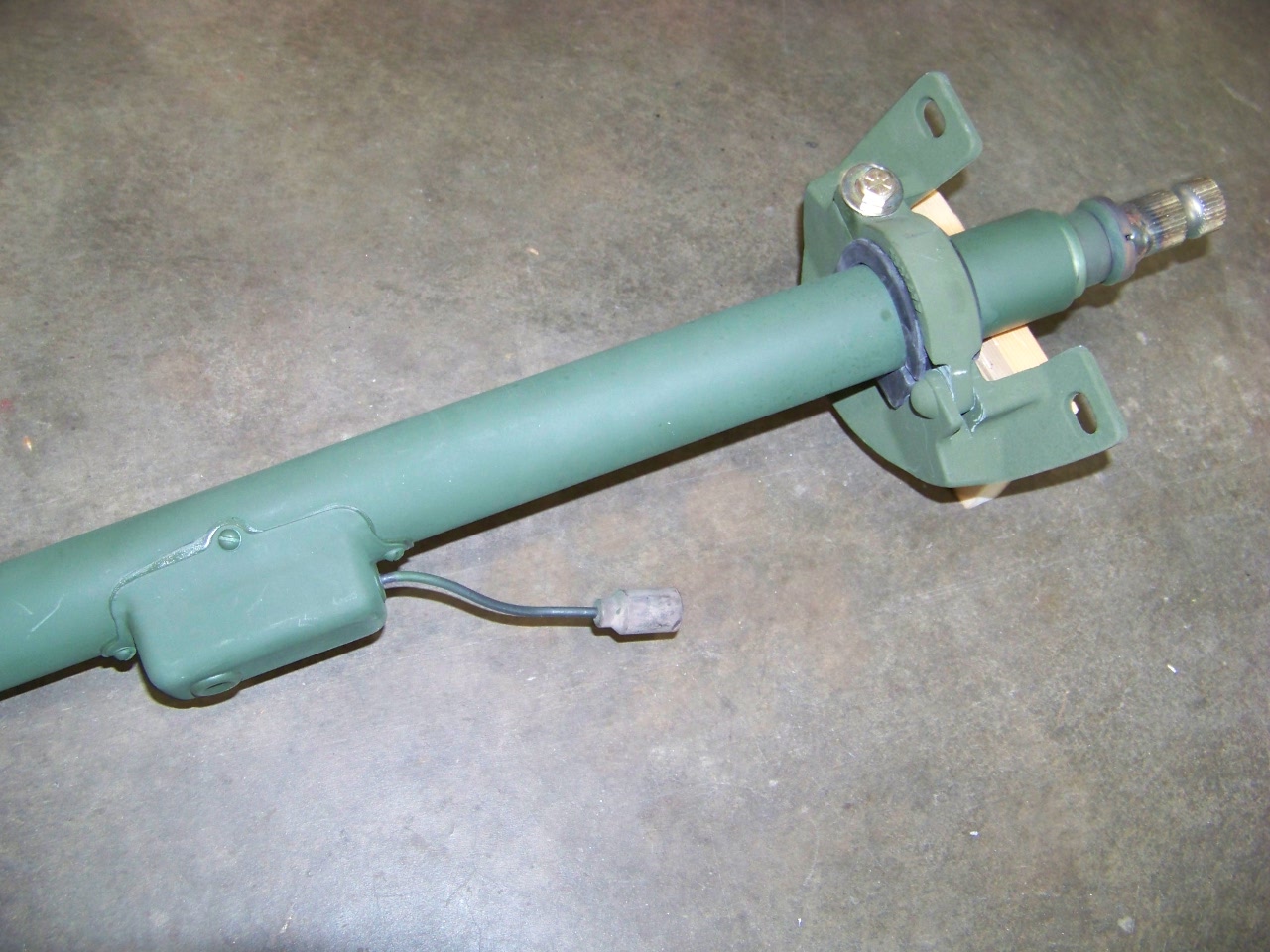
FIG 17 |
FIG
18 |
- Mount reservoir on firewall. It mounts using the captive nuts that were for the voltage regulator in a previous life FIG 17. (Note: some newer cabs may not have these holes, see picture for location.) (bag #5)
- There is the option of lowering the hole where it goes through the firewall. Try it with the existing hole first unless you are sure you want more belly room. In that case you can lower it where it goes thru the firewall up to 6 1/2" by removing the top rivet from the cab mount plate and cutting away the upper part of the mount FIG 17. This will raise the steering wheel a few inches. Do not punch out the round stamped area of the firewall, it is for when this cab was used on a 5 ton and will not line up correctly. You can adjust the upper column in and out since the lower shaft has a sliding connection.
- Attach mount to new column as shown with 2” sticking out past rubber FIG 18. (shown upside down) It goes in the same orientation as the one on the dash FIG 20. Put the column in the hole in firewall and secure at dash temporarily. Hold lower end in center of hole and mark bolt holes, then remove column and drill 1/4” holes.
NOTE: Before final installation of the column mount the wheel to it. Hold column upright with bottom of shaft on floor and push down on column to relieve pressure on the plastic shipping spacer, remove it and install wheel. While handling the upper column, use care so that the shaft stays towards the top end so the horn contact does not get broken. If you feel any resistance in the shaft, turn it very gently while letting it move back up into position.
- Now install column and secure at firewall.(bag #4)
- Install lower steering shaft and tighten bolts to specified torque. 3/8" bolts are 48 ft lbs, 7/16" bolts are 75 ft lbs. The upper joint of the lower shaft can be used to adjust the rotational position of the steering wheel.
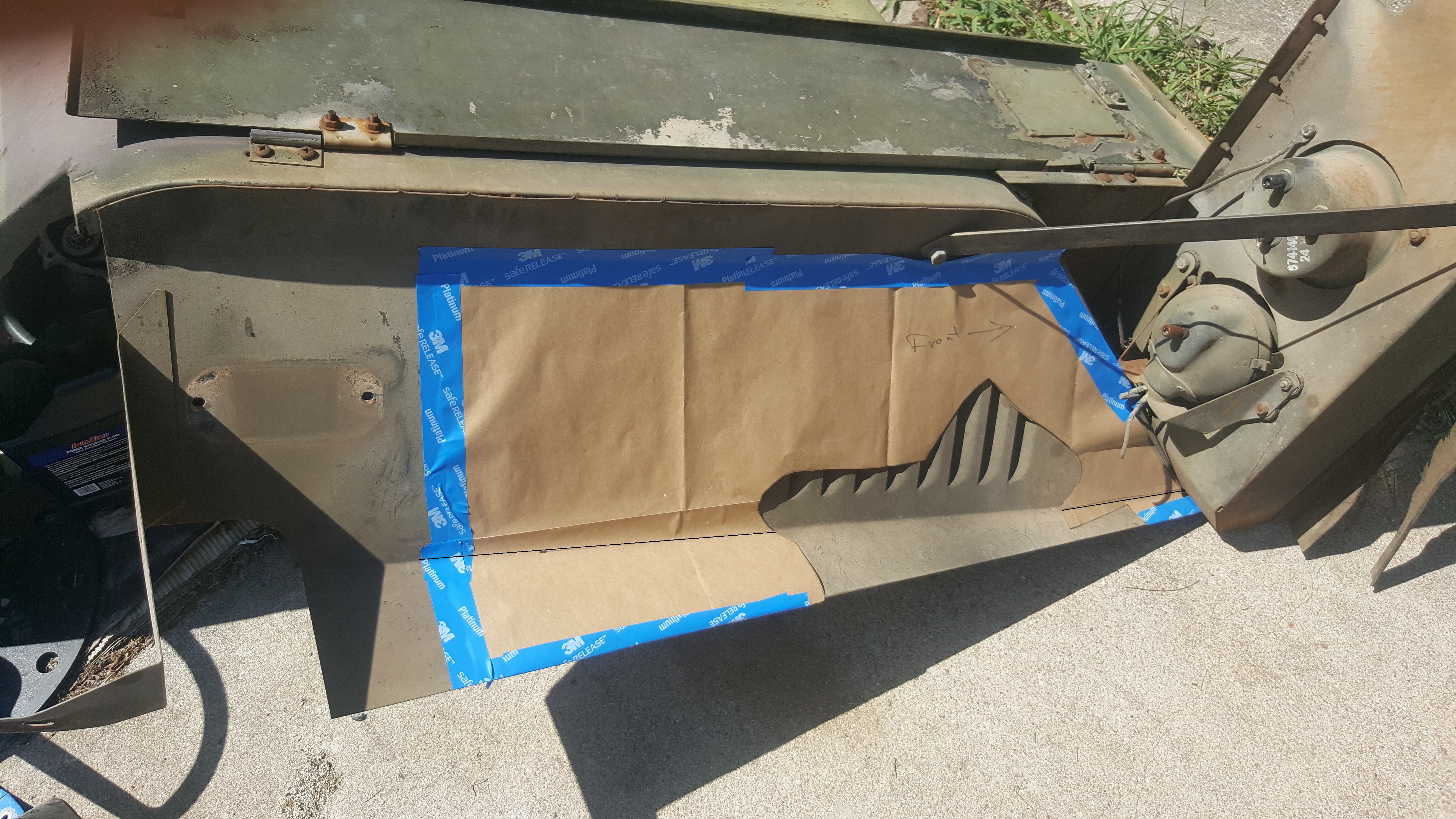
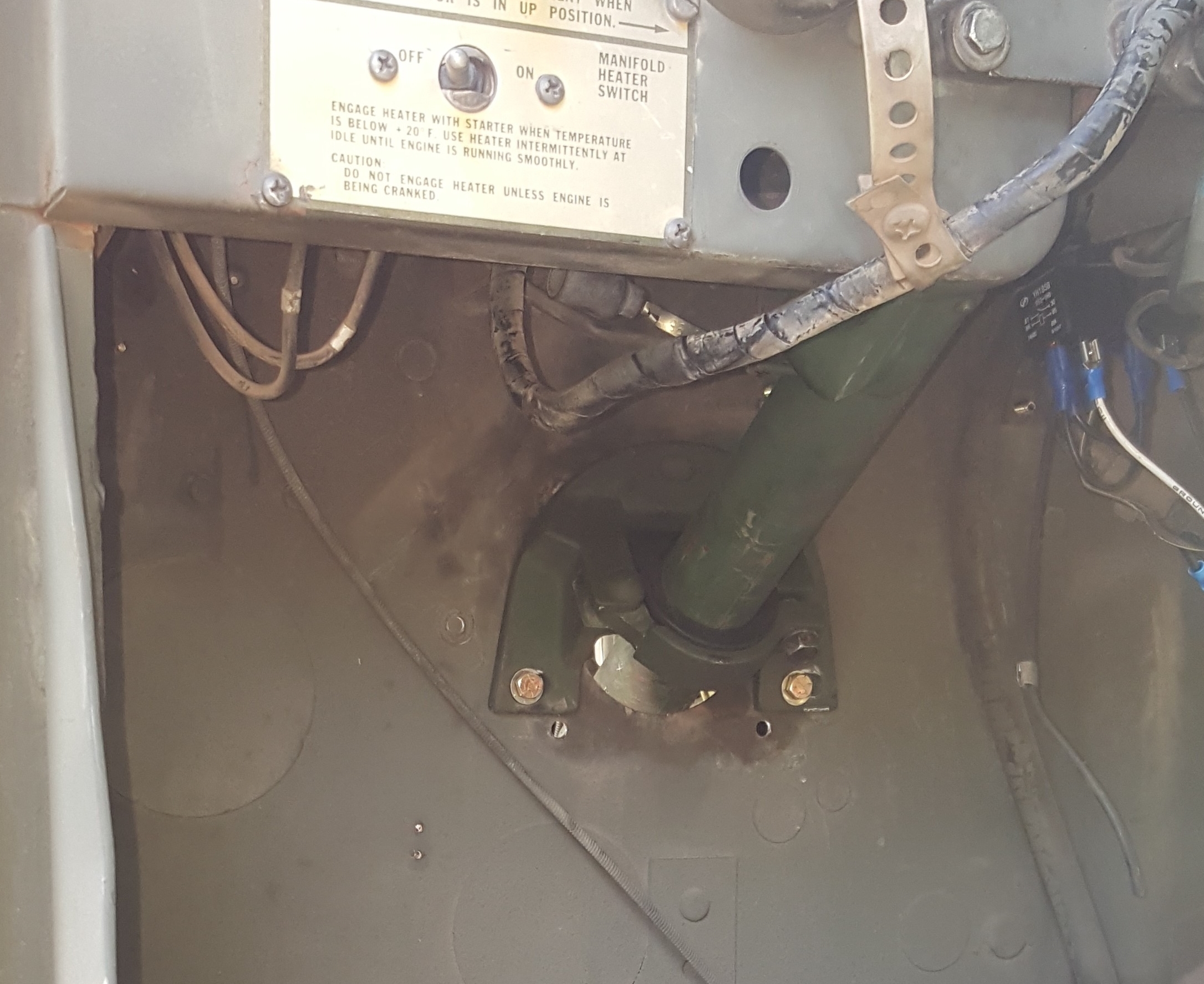
FIG 19 |
FIG 20 |
- FIG 19 shows the position of the template for the cutout of the inner fender.
- Run suction hose from the bottom of the reservoir to the pump, fitting on pump should be at about 4 o'clock position. (this hose is meant to lay inside frame) Use Teflon tape where the suction hose fitting (3/4" pipe thread) goes into the pump. Short pressure hose goes from the smaller port of the pump to the line facing forward. Put some oil on the "O" ring of this fitting at the pump. Return line goes from the line on the box facing the rear, to the side of the reservoir. The return line fitting on reservoir can face either side, but reservoir and bracket should be able to be used in the position they are right out of the box. All hoses should now be on and you can fill the reservoir so that air will begin to come out of system.
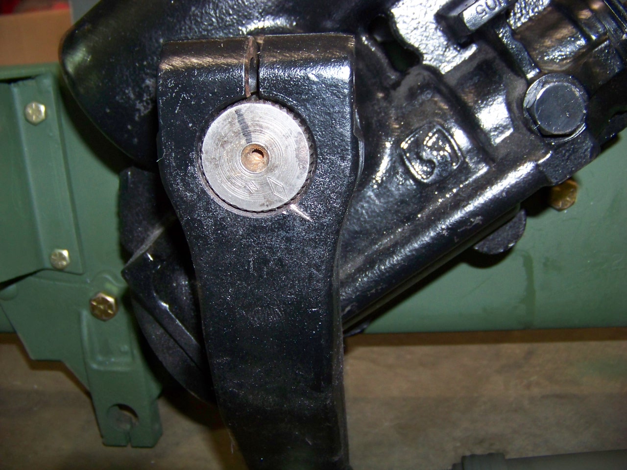
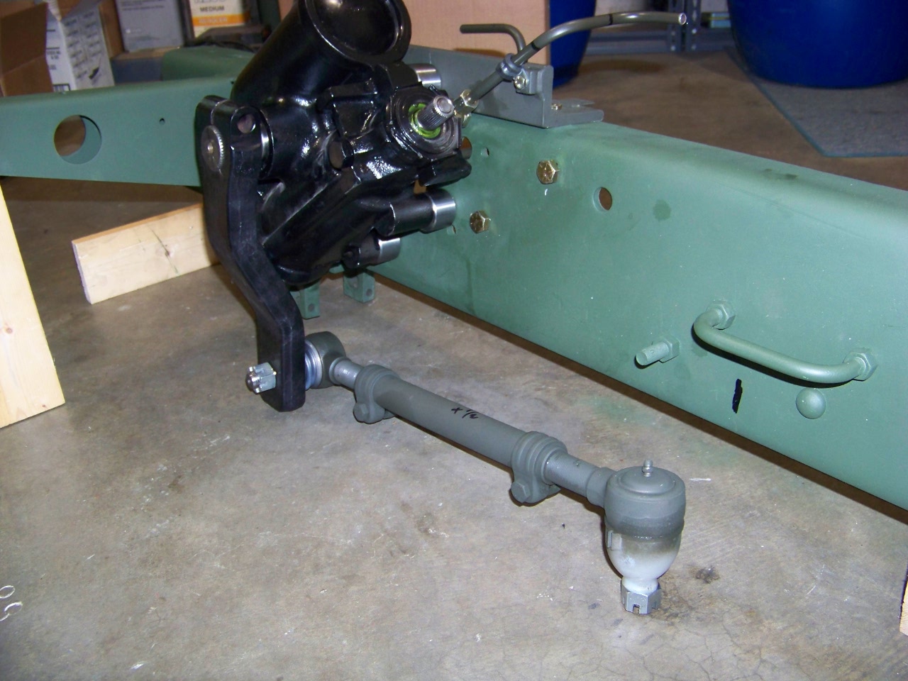
FIG 21 |
FIG 22 |
- Install Pittman arm so that the diamond mark on the shaft is lined up with the chisel marked line FIG 21. Torque the pinch bolt to 150 ft lbs.
- System should hold about 2-3 quarts of power steering fluid, check it often and do not overfill (about 1 1/2" below top); the 710 box is hard to get all the air out of. Keep enough fluid in the tank and before putting the drag link on and with the engine off, cycle the box from stop to stop about 10 times. Next check the reservoir tank fluid level and add, start the engine, (keep cap on with engine running) and cycle it another 10 times. This will get most of the air out and driving it will eventually get the rest. It should perform OK now but will be at its best after a couple of days of driving. If the pump seems hard to prime, just loosen the fitting where the pressure line attaches to the steel tubing. Just crack it open a little (very carefully) and let some air out then tighten.
- Install drag link. It is adjustable, but is set where it should be and you should not have to change it. Torque end joint nuts to 75 – 105 ft lbs and then turn nut to next cotter pin slot.
NOTE: Mount the drag link so that the slots on the adjusting sleeve are on the bottom so it does not hold water. FIG 22
You will need to extend the horn wire from the front into the cab to the contact. Grounding of the column will be also necessary.
If you have any problems or questions, feel free to give me a call at (410) 549-6649.